- Published 23 May 2024
- Last Modified 23 May 2024
- 5 min
What is UART?
Find out all you need to know about UART microcontrollers and protocols, how they work and what you can use them for.


Discover all you need to know about UART microcontrollers and protocols, how they function, and their practical applications.
UART, or universal asynchronous receiver transmitter, is a crucial component embedded within physical circuit boards, facilitating the exchange of data between devices. Recognized as a device-to-device communication protocol, UARTs were pioneers in ensuring secure and dependable data transmission.
While technological advancements have introduced alternative protocols, UART chips remain a cost-effective solution for integrating a straightforward serial protocol into circuit boards.
This guide will delve into the evolution of UART technology, elucidate its operations, and explore its diverse applications.
What Constitutes a UART Chip?

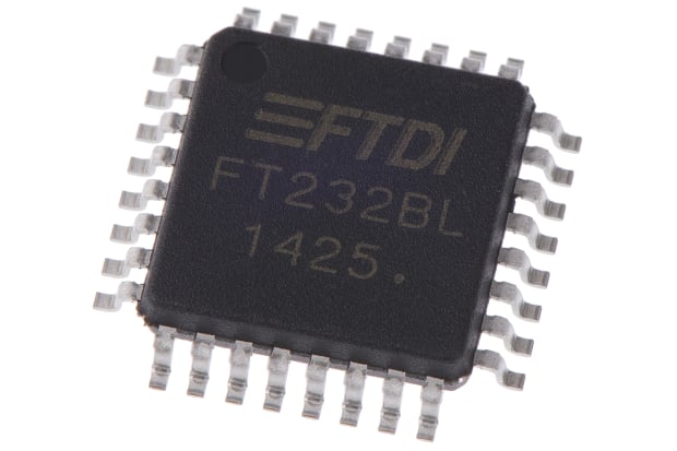
A UART chip, a tangible element, is integrated into circuit boards to enable data transfer. Typically, two UART chips are employed within a circuit board to facilitate bidirectional data transmission between buses.
UART chips accomplish this task by dissecting information into bits and transmitting them individually. Notably, this transmission can be initiated or halted at any point, hence the inclusion of the term "asynchronous" within UART.
Understanding UART Protocol
The UART protocol dictates the manner in which data is exchanged between UART chips. Asynchronous in nature, the UART protocol operates independently of a clock for synchronizing and regulating data transmission between devices.
Rather than relying on a clock, transmitting UART chips append start and stop bits to data packets received from buses. These bits signal to the receiving UART chip the commencement and culmination of data transfer. Users have the flexibility to configure UARTs within circuit boards to regulate the speed and frequency of data transmission, referred to as the baud rate.
The History of UART
The inaugural UART chip emerged from the ingenuity of engineer Chester Gordon Bell, marking a significant milestone in the realm of data processing. Initially, these chips were substantial, akin to the size of an entire circuit board, tailored for computer programmable data processing.
By the 1990s, UART technology underwent refinement, enhancing data transfer velocity and security through the integration of on-chip buffers. Subsequent decades witnessed further evolution, aligning UARTs with the advancements in serial bus technology, aimed at expediting the accurate transmission of data.
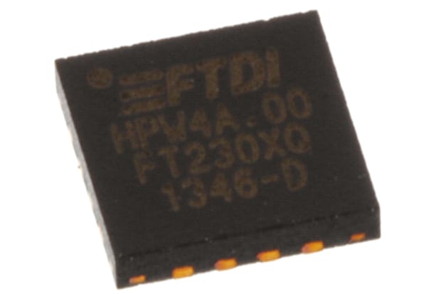
This evolution birthed innovations such as USB to UART connectors, serving as bridges between devices connected via USB and UART. Widely embraced as alternatives to RS232 ports, these connectors offer direct interfacing with microcontrollers, rendering them more adaptable and versatile.
Modern-day iterations of UART microcontrollers encompass:
- Raspberry Pi UART: Comprising models such as the PL011 and the Mini UART, Raspberry Pi UART caters to diverse applications. While the Mini UART primarily interfaces with the Linux console, the PL011 extends its utility to Bluetooth applications. A distinguishing factor between the two lies in data transfer stability, with the Mini UART reliant on frequencies from the core GPU, potentially jeopardizing data integrity. In contrast, the PL011 embodies more advanced and stable technology, ensuring secure data transmission.
- Arduino UART: Serving as a microcontroller or programmable circuit board, Arduino employs UART data transmission. Despite its relatively slower data transmission rate compared to alternative technologies, Arduino UART garners popularity due to its user-friendly nature and the abundance of online tutorials and resources, making it a preferred choice among DIY enthusiasts.
How Does UART Work?
UART functions by exchanging data signals, or packets, between two parallel chips interconnected via two wires. These chips, distinguished as transmitting and receiving UARTs, facilitate the transmission and reception of data.
Each chip interfaces with a data bus within the device, facilitating data transmission or reception. The UART protocol operates as follows:
- The transmitting UART chip receives signals from the data bus in parallel, mirroring the data sent by the bus.
- Upon reception, the transmitting UART chip supplements the received data (referred to as the data frame) with a start bit, parity bit, and stop bit to prepare for transmission. These bits, represented as either 1 or 0, demarcate the initiation and termination of data transmission, embodying the asynchronous nature of UART data transmission.
This amalgamation forms a data packet comprising:
- A start bit, triggering a voltage drop to commence data transmission.
- The data frame, comprising five to eight data bits, represents the actual content being transferred.
- The parity bit serves as a data quality check. The receiving UART scrutinizes this bit to ascertain data integrity. A parity bit reading 1 necessitates an even count of data bits in the frame, while a reading of 0 indicates an odd count. Discrepancies between the data and parity bits signal potential data loss during transmission.
- The stop bit signals the cessation of data transmission, causing the voltage to rise.
- Subsequently, the entire data packet, commencing with the start bit and concluding with the stop bit, is dispatched to the receiving UART chip at the predetermined baud rate.
- The receiving UART chip discerns and eliminates the start, stop, and parity bits, preserving the data frame. This frame is then disseminated, bit by bit, to the receiving data bus, completing the transmission process.
How to Use UART
To utilize UART protocols, two UART chips must be interconnected via two wires. Additionally, each chip must be linked to individual data buses within the circuit board. Effective utilization of UART necessitates adherence to the following guidelines:
- Ensuring a minimum 90% similarity in the sending and receiving frequencies (i.e., the baud rate) between UART chips mitigates the risk of data corruption or loss, ensuring stable and secure data transmission.
- The data frame within UART packets is constrained to a maximum of nine bits, limiting its suitability for complex communications.
- While users can adapt the parallel nature of UART protocol to modify data packet structures, these systems lack support for multiple master-slave communication models.
Due to its simplistic setup, UART finds myriad applications, ranging from GPS units to wireless connections and internal computer processing. Abundant resources and support for UART protocols further bolster its appeal, rendering it a favored choice for DIY circuit board enthusiasts seeking to transmit data effectively.
How to Test UART
The most effective method of testing entails employing a script to evaluate UART functionality. These scripts are readily accessible online and facilitate a test mode to assess data transfer efficacy through UART, thereby confirming successful data transmission.
Alternatively, dedicated test programs are available for purchase, offering comprehensive analysis of data transmission efficiency and stability within UART. These programs simulate various scenarios to scrutinize all facets of UART operation, promptly flagging any anomalies in functionality.
Related links
- A Complete Guide to Anemometers
- A Comprehensive Guide to Air Quality Monitors & Sensors
- How to Solder - A Beginners' Guide to Soldering
- Understanding TRIACs: A Comprehensive Guide
- A Complete Guide to Timing Belts
- The Complete Guide to Breadboards
- A Complete Guide to PID Temperature Controllers
- A Comprehensive Guide to Thermal Fuses

